Engineering takeaways
- Map every motion, process and safety signal before disconnecting the legacy control.
- A successful retrofit starts with measured machine condition and documented interfaces, not a controller shopping list.
- Retain a tested rollback path until safety, motion, process and production acceptance are complete.
Compatibility checklist
- A step-by-step engineering method for replacing a legacy laser controller while retaining only verified mechanics, drives, safety devices and auxiliary systems.
- Record machine model, serial number, year, working area and automation options.
- Identify controller, industrial PC, servo drives, encoders, fieldbus, remote I/O and height-control hardware.
- Collect electrical, pneumatic, gas, cooling, extraction and safety drawings; mark undocumented changes.
- Measure mechanical accuracy, backlash, gantry squareness, slat-bed condition and axis performance before increasing speed or power.
- Define materials, thickness range, assist gases, daily output, quality limits and target laser power.
Hardware and integration scope
- The controller, industrial PC, servo interfaces, height control and laser I/O must be engineered as one architecture.
- Document the rated interfaces and utilities named in the project scope: A step-by-step engineering method for replacing a legacy laser controller while retaining only verified mechanics, drives, safety devices and auxiliary systems.
- Industrial PC or operator console, controller and licensed software matched as one supported set.
- Servo/encoder interfaces, fieldbus couplers, remote I/O, safety relays and galvanic isolation where required.
- Capacitive height control, cutting-head signals, laser modulation, gas valves, chiller and extraction interlocks.
- Documented terminal numbering, cable shielding, grounding, spare I/O and service access for future maintenance.
Implementation workflow
- 01
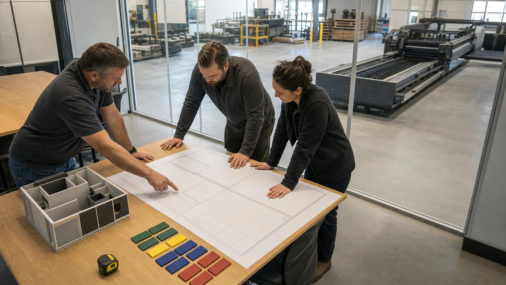
Define the decision: Record machine model, serial number, year, working area and automation options.
- 02
Capture the machine baseline: A step-by-step engineering method for replacing a legacy laser controller while retaining only verified mechanics, drives, safety devices and auxiliary systems.
- 03
Freeze the integration architecture: The controller, industrial PC, servo interfaces, height control and laser I/O must be engineered as one architecture.
- 04
Prepare the outage: The controller, industrial PC, servo interfaces, height control and laser I/O must be engineered as one architecture. Issue the retrofit architecture, I/O matrix, bill of materials, risk register, rollback plan and outage schedule.
- 05
Commission through controlled gates: Undocumented OEM PLC logic is the main source of late commissioning surprises. Commission axes at low speed, tune following error and height control, validate gas and laser signals, then build process tables progressively.
- 06
Prove production acceptance: Approve the migration only after safe stopping, axis accuracy and representative cutting are independently recorded.
Detailed engineering notes
Decision boundary
Create a machine dossier containing model and serial data, photographs of nameplates and cabinets, electrical revisions, PLC and CNC backups, drive/encoder types, alarm history and sample parts. Record the current cut quality and cycle time so the retrofit has a measurable baseline.
Reusable assets and integration limits
The controller, industrial PC, servo interfaces, height control and laser I/O must be engineered as one architecture. The frame, gantry, rails, drives, motors, extraction, gas train and automation should be assessed independently. A part that powers on is not automatically suitable for higher acceleration, a different control loop or higher laser power.
Interface evidence
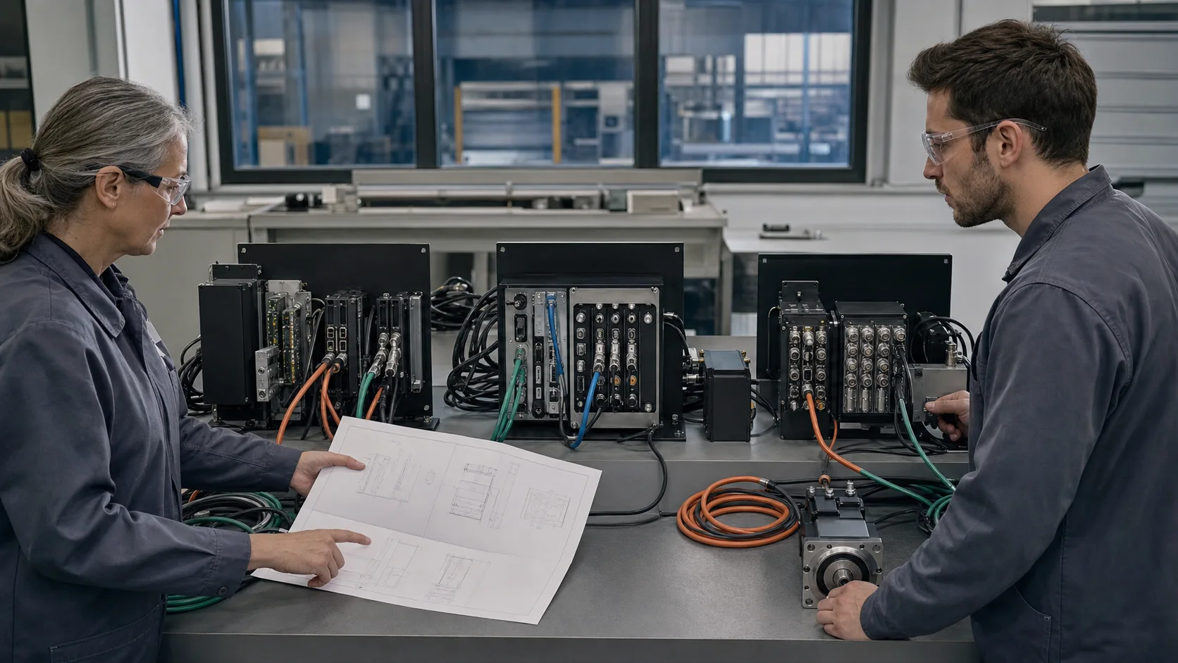
Identify controller, industrial PC, servo drives, encoders, fieldbus, remote I/O and height-control hardware. Industrial PC or operator console, controller and licensed software matched as one supported set.
Safety case
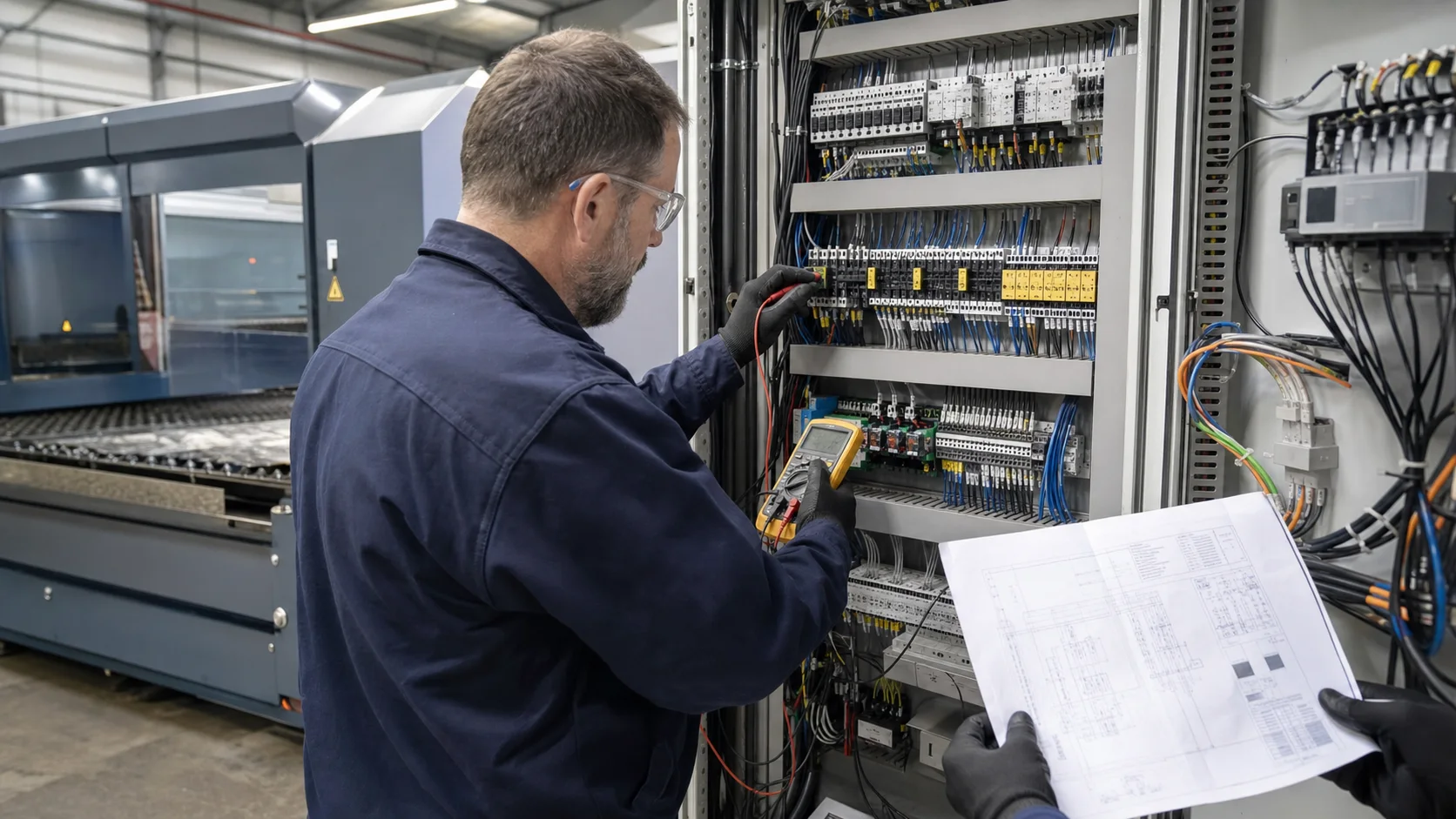
Undocumented OEM PLC logic is the main source of late commissioning surprises. Trace emergency stops, enclosure doors, light curtains, laser-enable chain, gas pressure, cooling flow, extraction and motion brakes. Each device needs a defined safe response and a recorded validation test after wiring changes.
Controlled commissioning
The controller, industrial PC, servo interfaces, height control and laser I/O must be engineered as one architecture. Verify power distribution and protective earth first, then I/O, fieldbus, axis direction, limits, homing, low-speed motion, servo tuning, height control, gas, laser enable and finally cutting. Do not combine first motion and first laser emission into one test.
Production proof
Approve the migration only after safe stopping, axis accuracy and representative cutting are independently recorded. Use the customer's normal materials, thicknesses and quality criteria. Record nozzle, focus, gas, power, speed, piercing and inspection results, then compare repeatability across more than one sheet.
Handover and support
A common project question is: Can the old servo drives be retained? Engineering answer: Sometimes, but only when command interface, encoder feedback, fieldbus, safety behavior and tuning access are compatible and supportable. Train operators on daily use and maintenance staff on backups, alarms, I/O diagnostics and safe replacement procedures. Store the final drawings and software image in at least two controlled locations.
How to Retrofit a Laser Cutting Control System
laser control retrofit: A step-by-step engineering method for replacing a legacy laser controller while retaining only verified mechanics, drives, safety devices and auxiliary systems. The controller, industrial PC, servo interfaces, height control and laser I/O must be engineered as one architecture.
- Can the old servo drives be retained?
- Which I/O and encoder signals must be measured before a control retrofit?
- Can existing axes and drives be retained with a new laser controller?
- How many outage days should cabinet rewiring and dry commissioning allow?
Risks and limitations
- Undocumented OEM PLC logic is the main source of late commissioning surprises.
- Treat an unresolved survey finding as a commercial and outage risk, not an assumption: Undocumented OEM PLC logic is the main source of late commissioning surprises.
- A new controller cannot correct worn rails, backlash, frame distortion or an unstable cutting bed.
- Bypassed or incompletely mapped interlocks create unacceptable personnel and equipment risk.
- Unverified licenses, firmware, servo compatibility or undocumented OEM logic can extend downtime.
Acceptance criteria
- Approve the migration only after safe stopping, axis accuracy and representative cutting are independently recorded.
- Record the agreed evidence, limits and operator handover in the final acceptance file: Approve the migration only after safe stopping, axis accuracy and representative cutting are independently recorded.
- All emergency stops, doors, light curtains, pressure, cooling and extraction interlocks stop hazardous motion or laser emission as designed.
- Axis travel, homing, limit switches, following error, repeatability and contour accuracy meet the agreed baseline.
- Cut coupons cover representative materials and thicknesses, including holes, corners, common-line cuts and piercing.
- Backups, drawings, parameter sets, licenses, spare-parts list, operator training and maintenance handover are complete.
Frequently asked questions
Can the old servo drives be retained?
Sometimes, but only when command interface, encoder feedback, fieldbus, safety behavior and tuning access are compatible and supportable.
Can the final hardware be selected from photos alone?
No. Photos help identify the machine, but drawings, controller/drive data, I/O measurements, safety logic and mechanical checks are required before a binding scope.
How is retrofit downtime controlled?
Pre-engineering, cabinet preparation, software staging and acceptance planning are completed before shutdown. The schedule still includes contingency for undocumented wiring or failed legacy parts.
Related technical guides
Official technical references
Platform names describe product families, not guaranteed retrofit compatibility. Final software, controller and license selection follows a machine survey.